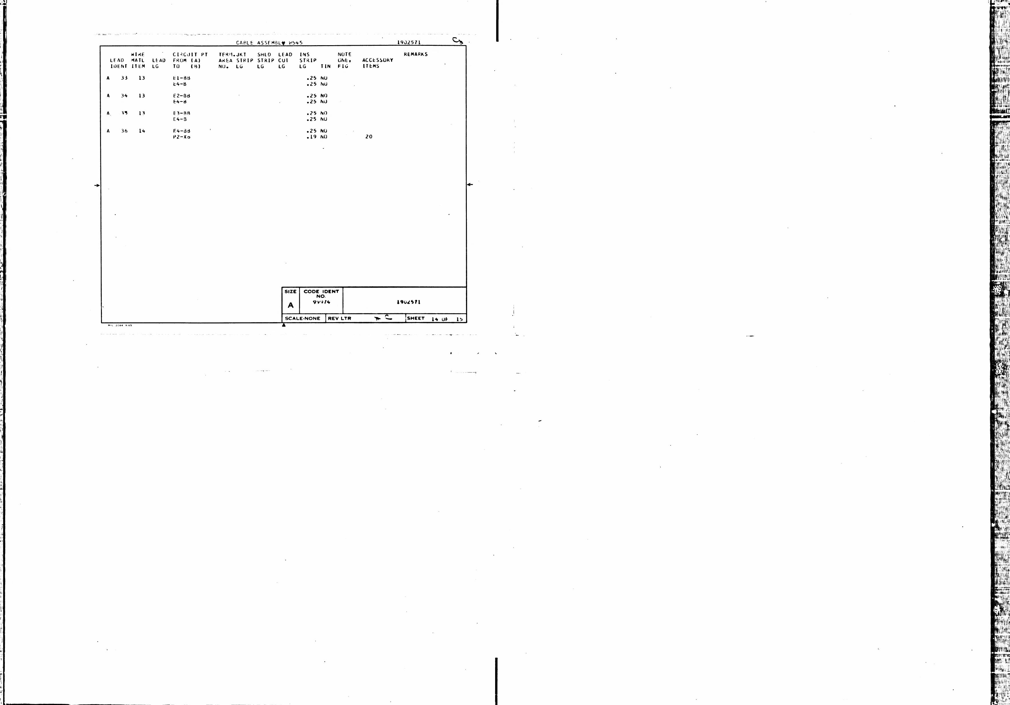
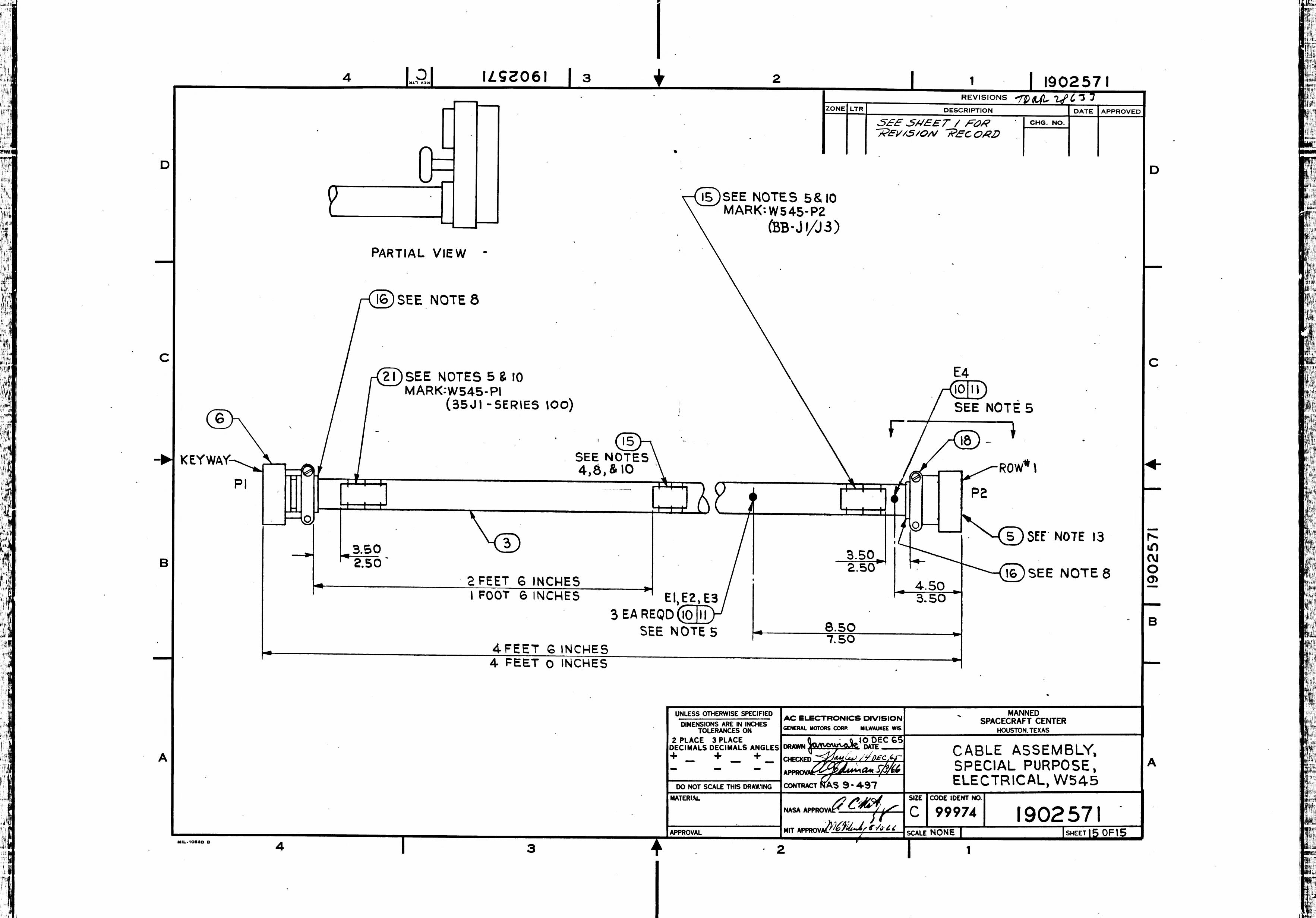
| gemini | * **Step 1:** Locate the relevant sheet showing the overall assembly and dimensions. This is sheet 15 of 15.
* **Step 2:** Identify the components mentioned in the question.
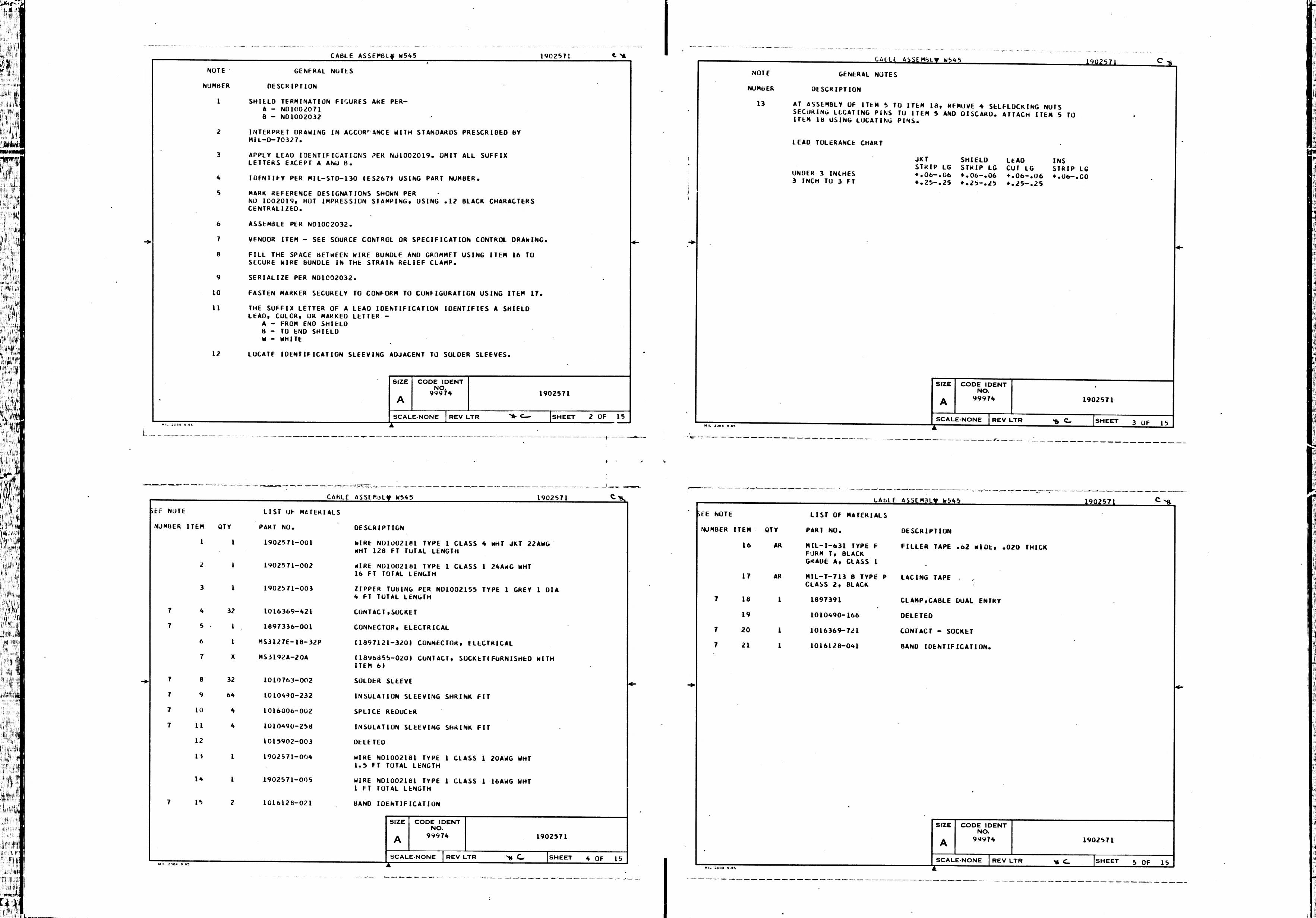
* "part 1897336-001" is identified in the "LIST OF MATERIALS" on sheet 4 of 15 as ITEM NO. 6, which is a "CONNECTOR, ELECTRICAL". On the main drawing (sheet 15), item 6 is the connector labeled "P1" on the left side.
* "E1" is identified on the main drawing (sheet 15) as part of the callout "E1, E2, E3 (11)". This points to a component along the cable.
* **Step 3:** Find the dimension between these two points on the drawing (sheet 15). There is a dimension line extending from the face of the P1 connector (item 6) to the location of the E1, E2, E3 components (item 11).
* **Step 4:** Read the dimension value. The value is given as a range: "4 FEET 6 INCHES / 4 FEET 0 INCHES". In engineering drawings, this format typically represents MAX / MIN.
* **Step 5:** Extract the maximum length from the range, which is "4 FEET 6 INCHES".
* **Step 6:** Convert the dimension to a single numerical value. The title block states "UNLESS OTHERWISE SPEC | ✗ |